Description
GENERAL
Use
The Bag Filter is designed for the dry separation and recovery of powder from exhaust air of spray dryers.
Safety warnings
General
The bag filter is used for the dry separation and recovery of powder from the exhaust air as specified in this instruction.
Health and Safety Signs
Hot surfaces:
In case of touchable hot surfaces a warning sign shall be installed to avoid the risk of injury. The risks of burns shall be assessed based on the actual surface temperature, the position of the hot surfaces in relation to the work places and the prescribed personal protection equipment required on plant site, if any.
Personal Protective Equipment:
A mandatory sign shall be installed to indicate the necessity of personal protective equipment when entering the bag filter unit.
Restricted Area:
The access to the area around explosion venting must be restricted, hence proper sign must be provided.
Operation
Do not enter or open any port of the bag filter when in operation. The bag cleaning and fire extinguishing systems operates under pressure. Thus no part of this system must be dismantled unless it is established that the system is depressurized and thoroughly vented & risk free.
Service and Maintenance
Dusty atmosphere prevails inside the bag filter. Hence operational and maintenance personnel must be equipped with appropriate personal protective equipment, before entering the Filter Bag House.
Only skilled operating personnel in the maintenance of industrial machinery and familiar with the contents of this instruction shall perform service and maintenance of the bag filter.
Use only the approved cleaning liquids for cleaning the bag filter interior or other parts (i.e., water, dilute organic acids and CIP liquids recommended for stainless steel surfaces). No chlorinated water/ liquid to be used.
Preventive Measures Against Combustible Powders
The safety devices for explosion and fire prevention/protection must not be interfered with, changed or adjusted without the prior approval.
EQUIPMENT PERFROMANCE & TECHNICAL DATA
Dairy Bag Filter
The bag filter is designed to handle the exhaust air-flow from an existing dryer.
The standard bag filter is mainly used in the dairy industry to recover powder-fines from the different types of milk powders. These products include rather fine and sticky skim milk powder, more fatty powders like instant whole milk as well as light and fluffy protein powders made from casein or whey and permeate. The filter is designed furthermore for use in plants drying more hygroscopic whey and yeast products.
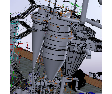
The bag filter is being used in conjunction with cyclones recovering any passing fine powder particles.
The bag filter is equipped as standard with an alternating pneumatic pulse system for the de-dusting of the bags in counter flow with the process air. Applying the technology of venturi’s above the filter bags reduces significantly the need for compressed air.
A fluidizing section is provided at the base of the cone to air the movement of powder from the bag filter, the fluidizing section shall also be used to circulate warm air through the system when the dryer is shutdown for extended periods like weekends allowing the preservation of materials within the spray dryer. A fan and heater is provided.
To eliminate the risk of fire a fire extinguishing nozzle is built in the top of the bag filter that can be connected to a high capacity firewater-pump, and explosion vents shall be fitted to the main body. To complete the protection against fire risk.
TECHNICAL SPECIFICATION FOR FILTER BAG HOUSE
| Air amount maximum | Suitable |
| Inlet air temperature, approx. | 77-95 °C |
| Nature of product | Dairy powder |
| Filter area | Suitable |
| Operating pressure | 50 mbar; |
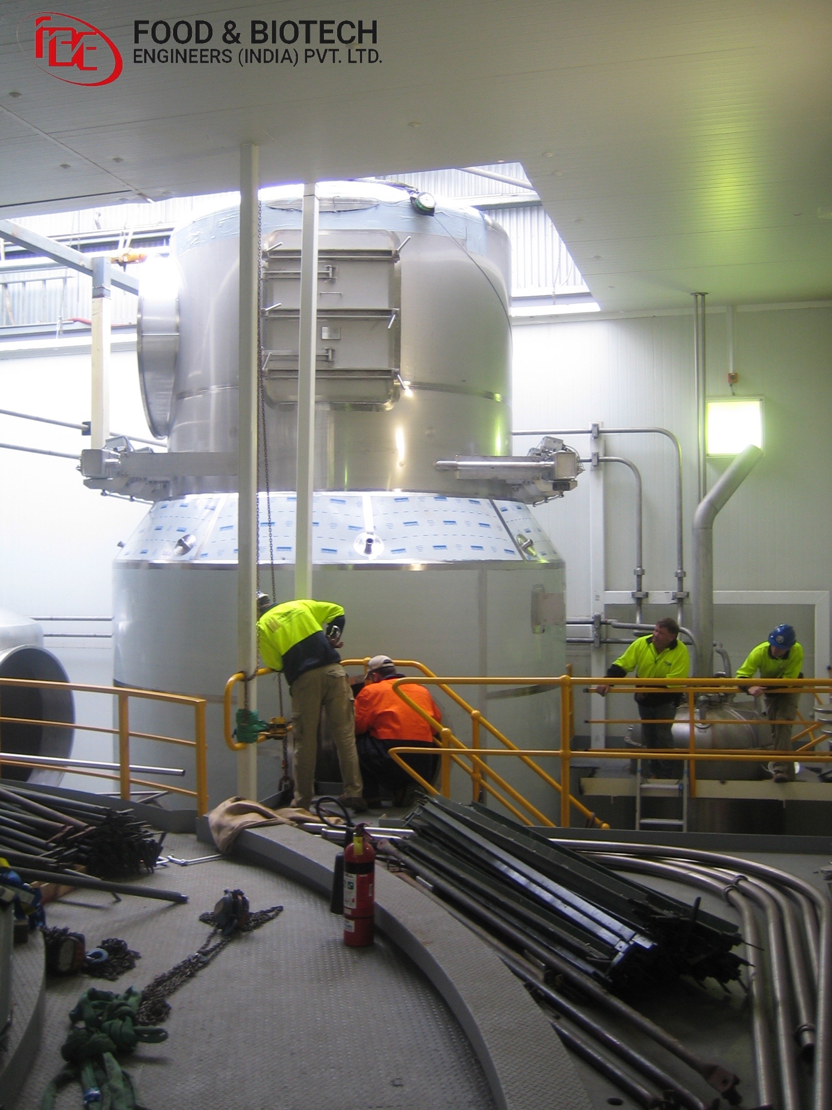
DESIGN AND FUNCTIONAL DESCRIPTION
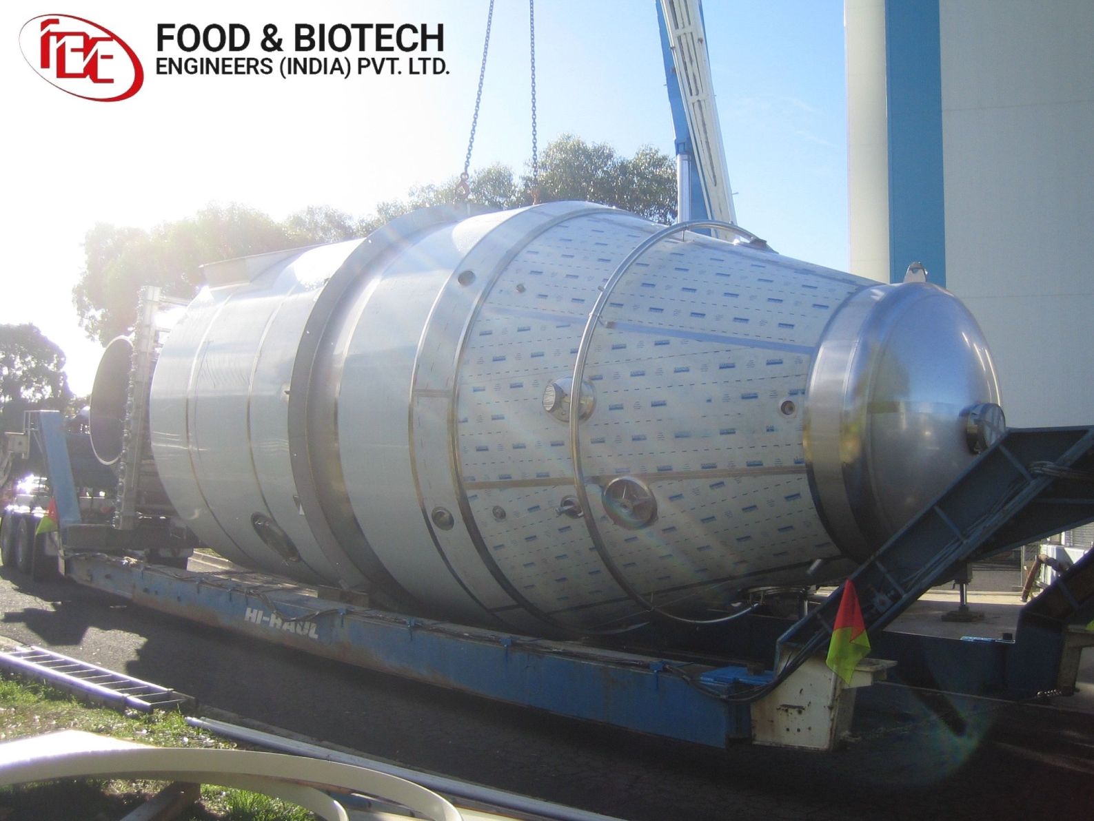
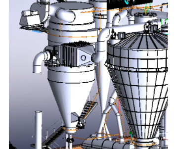
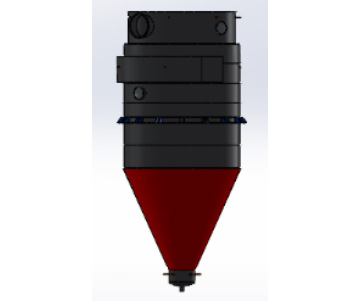
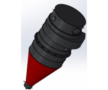
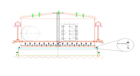
The complete bag filter comprises the basic bag filter housing described in this section and auxiliary equipment.The basic bag filter unit consists of the following main components:
- Cylindrical chamber and scroll type tangential inlet
- Outlet chamber
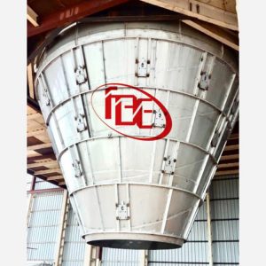
- Conical bottom
- Integrated Fluid Bed at bottom for cooling & efficient discharge
- Filter bags and wire cages
- Inspection and measuring device
- Control unit
- Bag cleaning system
The material of construction for bag filter in contact with product is made of stainless steel (AISI 304). The filter bags are made of heat-treated polyester or polypropylene.
Cylindrical chamber and Scroll type tangential inlet
The cylindrical chamber receives the product-laden air through a tangential inlet, which generates a cyclonic effect and thereby separates some product from air. The cylindrical chamber contains the filter bags and wire cages which are installed on the hole-plate. They separate the rest product from air by filtration. The whole unit is supported by a chamber ring.
Outlet Chamber
The outlet chamber consists of the two top covers, which is flanged to the cylindrical bag housing. One top cover at the time can be removed to facilitate the installation of filter bags and wire cages. The outlet chamber exhausts the filtrated air through the perpendicular outlet channel.
Conical Bottom
The conical bottom collects the filtrated product and leads it down to the product outlet
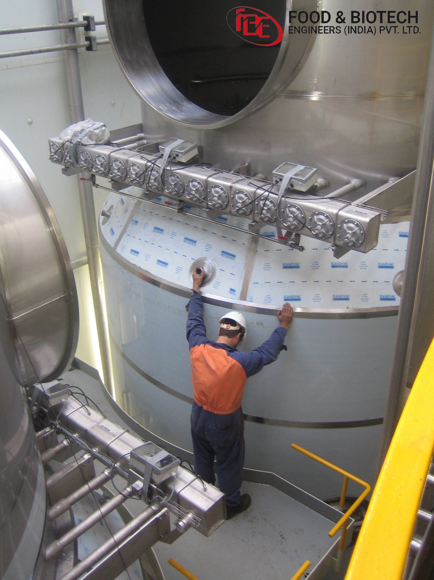
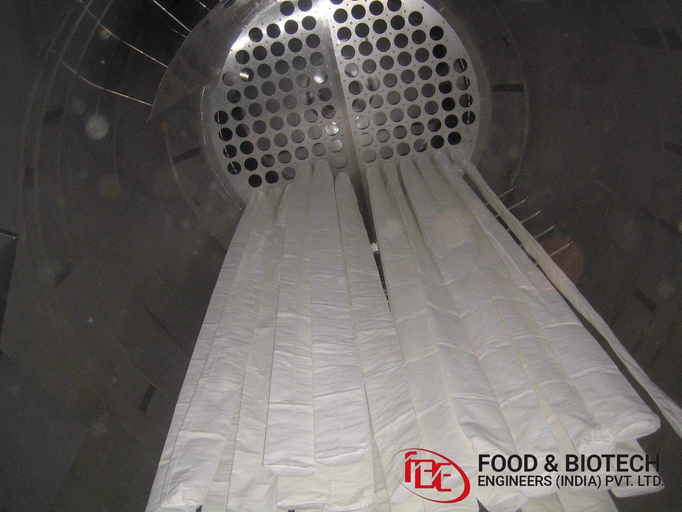
Filter bags and cages
The product is collected on the external surface of the filter bags, while the cleaned air flows through the filter medium.
The filter bags are held in position by stainless steel wire cages. Depending on the free height available above the clean air outlet chamber, the wire cages are fabricated in one, two or three parts. Couplings are provided to facilitate the assembly in case of two or three parts. It is important to prevent damage to the bags especially during mounting and dismounting.
Note:
The selection of wrong filter bag design, filter material or manufacturing techniques as well as damage caused by incorrect storage or installation will influence the separation efficiency.
Inspection and measuring devices.
The bag filter is equipped with inspection covers to facilitate inspection and allow access to the bag filter. Sight glasses with lamps are provided on the outlet chamber with a 45ᴼ displacement from the inspection covers to enable detection of leaking filter bags.
Two measuring branches are provided above and below the hole-plate for measuring the differential pressure across the filter bags.
Control Unit
The bag filter is equipped with two control units placed on each top cover the control unit runs all automatic processes on each of the bag filter top covers with a local CPU or an external CPU connected to the control unit via BUS-system.
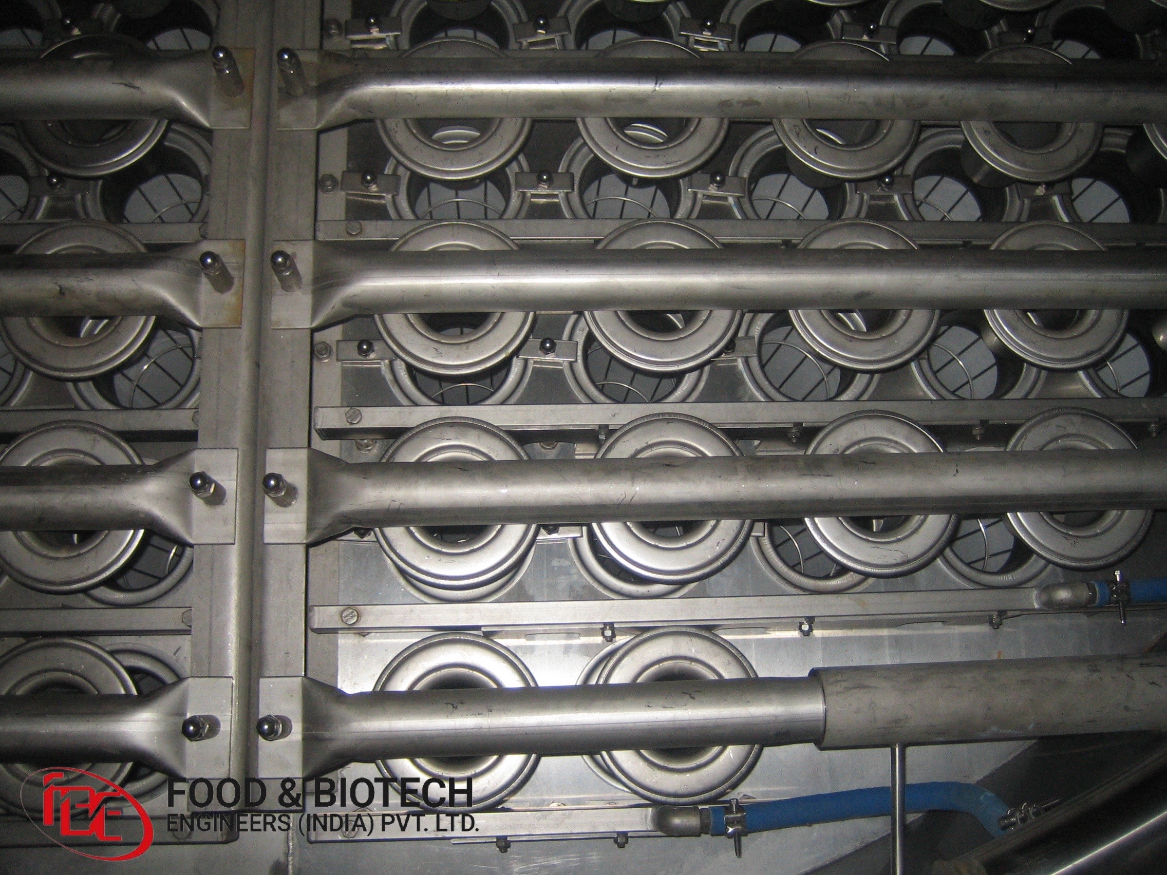
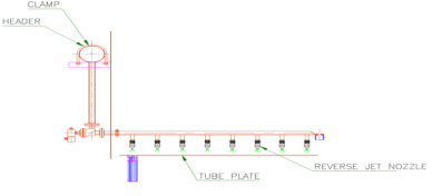
Filter bag cleaning system
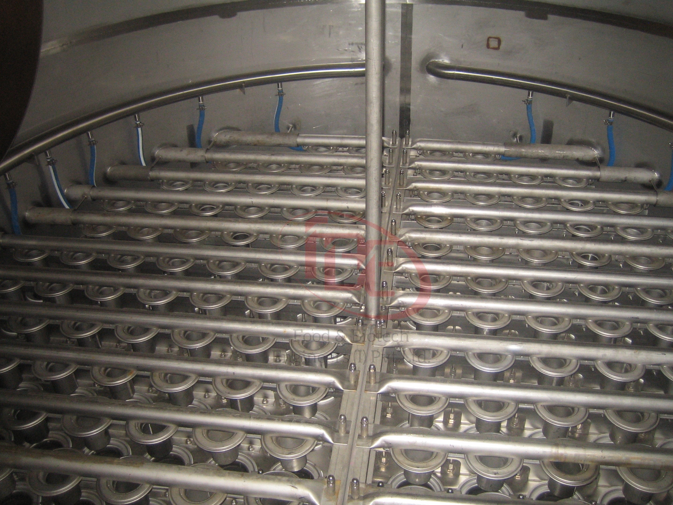
The bag filter is equipped with a fully automatic filter bag cleaning system. The cleaning of the filter bags takes place periodically during operation and is achieved by a compressed air pulse through the reserve jet nozzles system positioned above the bags.
The pressurized air is distributed from the manifold to the pneumatic activated diaphragm valve, through the lance pipe to the nozzle rod and finally to the reverse jet nozzles. The pressurized air enters the reverse jet nozzle through the distributor chamber and ejects through the annular slot. The guide body diverts the air into a flow of larger diameter and the flow is directed precisely into the filter element.
The reverse jet nozzle produces a pressure wave that continues along the entire bag length. Thereby, the bags are stretched and the adhering dust particles are thrown away into the bottom chamber and discharged through the product outlet.
The cleaning system is controlled by a time adjustable air impulse not the differential pressure across the hole-plate.
The pulse of cleaning air has a very short duration in the range of 0.1 sec to 0.5 sec, typically about 0.2 sec and the bag is therefore immediately pressed (sucked) back to the filtration position. The impulse jet cleaning system with its short pulses ensures low pressure drop conditions over the bags.
The filter bag cleaning cycle is determined by the following cycles:
| Impulse time | Time for cleaning of one bag |
| Pause time | Time between two impulses |
| Cleaning cycle time | Time for one cleaning cycle for all the bags |
The following times are the standard range and can be changed based on the requirements:
| Impulse time | 0.2 sec |
| Cleaning cycle time | 180 sec |
| Pause Time | 30 sec to 180 sec. |
The pause time adjustable
The following must be noticed in case the time intervals are changed:
- By decreasing the pause time, the compressed air consumption increases proportionally and the cleaning of the bag is intensive.
- By increasing the pause time, the compressed air consumption decreases proportionally.
- The impulse time is pre-fixed and may under special circumstances be adjusted based on product and/or process requirements.
NOTE:
The pressurized air for the bag cleaning system must meet the requirements stated.
AUXILIARY EQUIPMENT AND SYSTEMS
The following equipment and systems are installed on the basic bag filter considering the product and / or process requirements.
- Bottom cone & part of cylindrical portion, Air Insulation Panel
- Fluidized bottom
- Electromagnetic Hammers
- Explosion protection devices
- Disc Fluidizer at bottom cone
- Fire extinguishing system
- CIP equipment
Bottom cone & part of cylindrical portion, Air Insulation Panel
In order to avoid condensation, this causes deposits on the bottom cone wall
Fluidized Bottom
The key purpose of the fluidized bottom is to achieve a constant product outlet from the bottom of the bag filter housing. The air for the fluidized bottom is product contact air and is filtered and dehumidified.
Electromagnetic Hammers
In order to release any deposits, the bag filter bottom cone is equipped with pneumatic hammers. The necessary vibration is transferred to the wall surface via a plate that is impacted by an Electromagnetic Hammer.
Explosion protection devices
The safety devices against powder explosions are defined and finalized individually based on the potential danger in each case. Refer to separate instructions for the actual protection devices compiled in the plant instruction manual.
Pressure Relief Venting
Pressure relief venting introduces a weak element in the bag filter, relieving the internal pressure in case of explosion. The venting area is primarily determined based on the product characteristics and the effective volume of the bag filter. The vent doors/panels are installed on the process air inlet duct to the cylindrical part. A sensor monitors the status of the vent doors/panels.
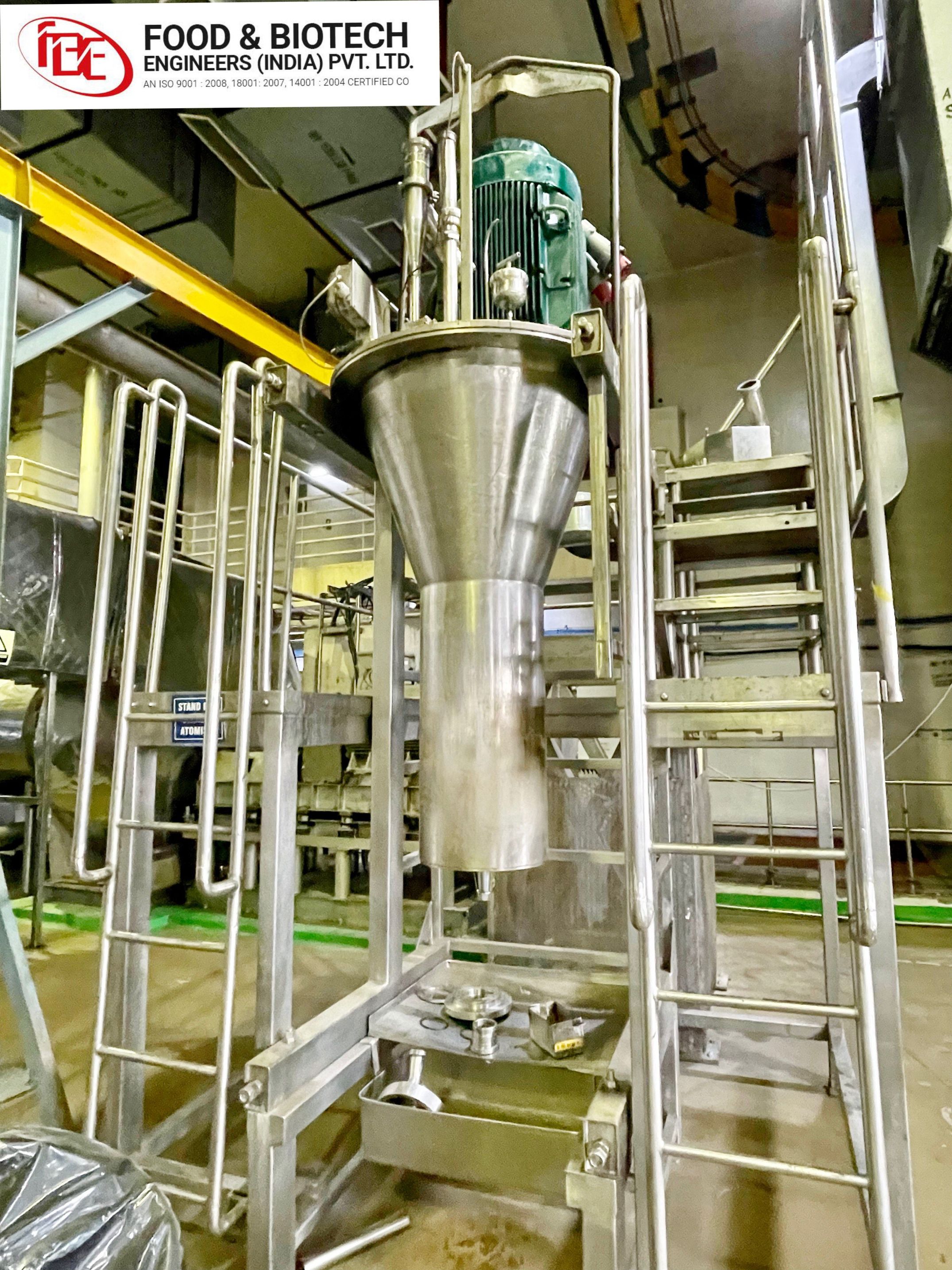
Disc Fluidizer at bottom cone
Aeration loosens up the product allowing it to flow easier. Minimum back pressure puts air energy where it is need the most- in the conical portion.
The fluidizer disk forces air to move along the bin wall freeing up product & assuring good cleanout. And also keeps the product flowing without allowing it to compact or plug. Disc seals tightly against the silo wall & prevents airline plugging.
Fire Extinguishing System
For reducing the fire hazard, the bag filter is equipped with fir extinguishing system. The main purpose is to cool the surfaces of the bag filter walls and the interior parts to prevent damages caused by excessive heat. However, the filter bags will inevitably be destroyed.
The nozzles are positioned in the outlet chamber and on the cylindrical part of the bag filter below the hole-plate.
A turbine nozzle is mounted on upper plenum. The flow of the water causes the nozzle head to rotate providing a swirling impact. A water level of 10 mm will be maintained on top of the hole-plate in order to minimize heat distortion.
The fire extinguishing nozzles mounted on the cylindrical part are closed by springs, and are opened by the water pressure when activated. The nozzle head is flush with the internal wall in closed position. When opened, the water sprays along the wall in a 360ᴼ pattern.
CIP (Cleaning in place) equipment
The Dairy bag filter is equipment with a CIP system to ensure cleaning of cylindrical parts and components in contact with the product. The equipment described below is installed as part of the CIP system. The number of nozzles Turbine type 5 on Top plenum & on spring retractable nozzles the actual bag filter unit.
Compressed Operated Air
Outlet chamber CIP
The outlet chamber is cleaned by turbine nozzles. The flow of the cleaning fluid causes the nozzle head to rotate providing a swirling impact.
Internal wall CIP
Retractable CIP nozzles are installed on the inner wall of the bag filter and in the plenum chamber of the fluidized bottom (if installed). The nozzles are closed by springs and are opened by the liquid pressure when activated (or opened and closed by a pneumatic actuator depending on type of nozzle installed). The nozzle head is flush with the inner wall in closed position. When opened, the nozzle ring becomes exposed and begins to rotate, spraying the cleaning liquid over the surface area. Once the liquid supply is stopped, the nozzle to its flush position.
ALARM SYSTEM
The following are the critical parameters related to the bag filter, which must be monitored and controlled:
Pressure drop across hole-plate (high alarm)
Measuring branch placed on bag filter above and below the hole-plate.
The performance of the bag filter is established considering the differential pressure across the hole-plate. The differential pressure across the hole-plate. The differential pressure shall not exceed the specified set point. Higher differential pressure indicates incorrect function of the unit and has damaging consequences and will always affect the capacity and performance.
Pressure in Outlet Chamber (low alarm)
Measuring branch placed on bag filter above the hole plate.
Measurement to protect the bag filter against excessive under pressure (vacuum).
Process Air Inlet temperature to bag filter (high alarm)
Measuring branch placed on duct.
Measured to protect the filter bags and gaskets against excessive temperature.
Air Inlet temperature to Cone heating section/ fluidized bottom (high alarm)
Measuring branch placed on duct or air supply unit.
Excessive air temperature will heat up the internal wall of the cone/fluidized bottom, which increases the risk of fire and explosion in case of powder deposits.
Process Air Outlet temperature to bag filter (high and high-high alarm)
Measuring branch placed on duct or exhaust unit.
Excessive air outlet temperature indicates a fire and initiates the fire extinguishing system
Water pressure for fire extinguishing system (low alarm)
Measuring branch placed on water supply control unit.
Alarm indicates water supply failure to the fire extinguishing system. Water supply must be established immediately: otherwise the plant shall be shut-down.
Status of explosion relief vents
Sensor placed on relief vents.
A sensor monitors the status of the doors/panels, if installed. Alarm is given in case of opening.
Pressure in compressed air manifold (low alarm)
Measuring branch placed on air manifold.
Alarm indicates compressor failure or leaking pneumatic system. Insufficient pressure will negatively affect the plant performance.